Bi square wi-fi antenna. Antenna Kharchenko: calculation and manufacturing. Additional materials and tools
Since 01/15/2014 in Moscow and the Moscow Region, on-air digital television broadcasting has been carried out only with DVB-T2 on UHF channels 24, 30 and 34.
For reliable reception of digital television channels in the city of Zhukovsky, Moscow Region, I first used an active indoor antenna "Delta", which did not always provide stable reception of a radio signal inside an apartment building.

The best results were shown by the previously published Triple Square antenna. At the same time, some inconveniences with the placement of an indoor antenna for reliable signal reception have not been eliminated. To install the antenna on the balcony facing the side of the transmitting center, a modification of the Kharchenko loop antenna was made. It is flat and easily placed on the wall of the balcony. The antenna is made of a single-core copper cable purchased from the Elektromaster store. To create it, you needed a ruler, a felt-tip pen, pliers, a 60-watt soldering iron and half an hour of free time. The insulation from the copper core with a diameter of 4 mm was removed only at the junction of the wire and the soldering of the television cable.
Kharchenko antenna calculation for DVB-T2 reception
The side of a square is easy to determine. It is equal to a quarter of the wavelength ( λ ) of the received radio signal.
For the first multiplex (30th channel) λ=300000/546(MHz)=549.45(mm). Accordingly, the side of the square a=λ/4, a=549.45/4=137(mm).
This antenna has a gain (in comparison with a dipole) of the order of 8 ... 10 dB, a wide bandwidth (confidently receives signals from 24, 30 and 34 television channels), is not demanding on manufacturing accuracy and is well consistent with a coaxial cable, like 75 Ohm , and 50 ohms. Distance between points a and b, where the central core and the braid of the television cable are connected, about 10 mm. The antenna gain can be increased by 2 ... 3 dB if it is equipped with a reflector (made of a metal sheet or mesh) located parallel to the antenna canvas at a distance h=0.21...027λ. Its exchanges should exceed, respectively, the width and height of the antenna web by 5 ... 10%. Due to the small area of the balcony, I was more satisfied with the “double eight”, but without a reflector. It provided high-quality reception of television digital and analog signals in the decimeter range.
As a reference, the table shows the radio frequencies of terrestrial analog and digital TV channels that can be caught on the terrestrial antenna in Moscow and the Moscow region.
Frequency plan for terrestrial analog television in Moscow and the Moscow region |
|||
Channel number | Channel frequency | Channel name | Note |
First channel | B I (1-3 channel) |
||
B I (1-3 channel) |
|||
Russia 2 (Sport) | B III (6-12 channel) |
||
B III (6-12 channel) |
|||
B III (6-12 channel) |
|||
UHF (21-69 channel) |
|||
Moscow region | UHF (21-69 channel) |
||
UHF (21-69 channel) |
|||
UHF (21-69 channel) |
|||
Home | UHF (21-69 channel) |
||
culture | UHF (21-69 channel) |
||
UHF (21-69 channel) |
|||
UHF (21-69 channel) |
|||
Channel 5 St. Petersburg | UHF (21-69 channel) |
||
UHF (21-69 channel) |
|||
UHF (21-69 channel) |
|||
UHF (21-69 channel) |
|||
UHF (21-69 channel) |
|||
UHF (21-69 channel) |
|||
Terrestrial digital television from 01/15/2014 is conducted only with DVB-T2 |
|||
First channel. Russia 1. Russia 2 (Sport). Russia 24. Culture. Carousel. Channel 5 St. Petersburg. NTV. OTR. TVC | UHF (21-69 channel) |
||
Ren TV. Saved. STS. Home. NTV plus sport. Star. Peace. TNT. TV3. Muz TV. | UHF (21-69 channel) |
||
Sports 1. Seeker. Russian novel. Sundress. Mother and Child. Moscow Trust. Music. Comedy. lifenews. Our football | UHF (21-69 channel) |
||
Successes in technical creativity!
Buy or not a decimeter antenna for watching digital TV? The question may seem strange, but on closer examination it becomes more reasonable. So, point by point:
- Where is the guarantee that the purchased antenna is worth the money spent on its purchase?
- When using a purchased decimeter television antenna in the country, you will most likely have to carry it back and forth with you in order to avoid theft.
- The need for such a device may arise spontaneously, somewhere on a picnic, and a trip to a special store is simply undesirable or impossible.
You can solve the problem with receiving the terrestrial television signal of the decimeter range using a home-made antenna for digital TV.
Types of dvb t2 antennas
Standard t2 dmv television - on the this moment newest mass used to transmit a digital signal. Its feature is a significant simplification of the receiving and transmitting devices through the use of decoding devices, the so-called tuners, some TV models already have a built-in digital signal decoding module. Significantly reduced signal power requirements, even a signal of low power is sufficient to reproduce a high quality picture, so there is almost always no need for an amplifier, it becomes unnecessary.
Antenna Kharchenko
Consider the device of a zigzag waveguide, the device of which was proposed by the enthusiast-engineer K. P. Kharchenko back in 1961 in the journal Radio. Outwardly, this device looks like a double rhombus or square adjacent to each other with open corners; at the junction points, the central core and the braid of the coaxial cable are connected.
To amplify the signal, you can use a metal reflector - a mirror that reflects a distant signal to the device. Digital Antenna Dimensions do-it-yourself depend on the wavelength of the received signal, it is clear that for the decimeter wavelength range and the dimensions of the dvb t2 antenna with your own hands will be within a few decimeters. The higher the reception frequency, the shorter the wave, the smaller the size. A room waveguide for receiving channels will have side dimensions of approximately 11 and 15 centimeters, overall external dimensions of 30 by 17 cm, and reflector dimensions of 50 by 50 cm.
For its manufacture, a little more than a meter of conductor is required - a copper or aluminum wire or tube with a diameter of 5-6 mm, preferably up to 10 mm or a strip, comparable width. The distance between the open points of the contact angles is 1–2 cm, the distance to the reflector is about 5–7 cm. This will be a long-range waveguide that allows you to receive 20 or more programs. The length of the television cable affects the operation of the antenna, if the cable is over 5-7 meters, you will need an amplifier, which one you choose.
- During operation, the waveguide should be turned towards the nearest transmitting station, during the first installation it is worth experimenting with the orientation of the device, achieving stable signal reception.
This type of antenna can be successfully used for receiving weak signal cellular network, only the dimensions of the device will be several times smaller. There are enough online calculators on the network to calculate specific parameters for each case.
Travel antenna
To make this homemade product, in addition to a plug for connecting to a TV receiver, you only need two identical empty half liter metal cans from drinks. Instead of a coaxial cable, you can take the usual "noodles" for landlines. In the region of the neck of each empty and dry can, one “noodle” wire is fixed with a self-tapping screw, or a braid of a television cable is screwed to one, and its core to the other. The banks are located on one straight line, the reception is adjusted by changing the distance between them from 1 to 8 cm, as well as the exact orientation in the direction of the emitter. The device should not be placed too close to the TV.
 If you don’t want to bother with any needlework, and it’s a pity to spend extra money, then you can arrange a very simple device. But it will work steadily where the signal level is quite high. You will need to know the digital broadcast frequency in order to determine the wavelength. To do this, 300 is divided by the number of megahertz of the “numbers” broadcast frequency and a fairly accurate value in meters is obtained. For a frequency of 480 MHz, the wavelength will be 0.625 m, and for 700 MHz - about 0.430 m. When even the broadcast wavelength is reluctant to recognize, we simply take 0.63 m, the largest possible.
A piece of coaxial cable is taken equal to the calculated wavelength, the ends are stripped from the outer insulation so that there is access to the braid. The cut piece is bent into a broken circle - there should be a gap of 1-2 cm between the stripped ends and fixed in any way, as simple as possible, even on a cardboard box. On the first side, the central core of another piece of the same cable is soldered, on the other - a braid. A plug is attached to the end opposite the soldering point. Connect and enjoy watching digital broadcasting.
In order to independently make an antenna for dvb t2 with your own hands, it will not take much time and special costs, but the result will please.
This design got its name from the name of the discoverer engineer Kharchenko. Structurally, the antenna consists of two squares connected at one of their vertices by disconnected sides. Power is supplied at the connection points of the squares, while the input impedance of the antenna is close to 50 ohms. This antenna has a huge bandwidth compared to its constituent elements - squares. To date, there are a huge number of options for the Kharchenko antenna, in which instead of squares, circles, triangles, etc. are used to compile its canvas. Previously, the Kharchenko antenna was used to work in TV and VHF bands, but today it is mainly made for amplification WI-FI signals, 3G and 4G.
This homemade design will easily cover the entire frequency range of modern digital television in the range from 470 to 900 MHz. At the same time, her parameters are simply amazing, and even a novice radio amateur can handle the coordination.
Homemade design consists of two squares. Both stand at the corners and connect at one corner. In the case of horizontal polarization, the figure eight stands upright, and with vertical polarization, it lies on its side.
The side of the square is determined by the formula, as the wavelength ( λ ) divided by four.

We bring the power cable to the points of convergence of the sides of the squares.
We make the "eight" from a monolithic copper wire with a cross section of 4 mm 2. Using pliers, bend the wire as shown in the figure below. We solder the ends together.
Border="0">
Then we need an aluminum plate 2 mm thick and 140 x 140 mm in size. She will act as a reflector. In the center of the plate, you need to drill a hole for the cable. Next, you need to fix the antenna in the center of the reflector at a distance of 3.6 centimeters, while the reflector with the antenna should not come into contact.

Having drilled holes for the clamps in the aluminum plate, I put the structure on the bracket from the satellite dish. Then I solder the cable, after passing it through the hole in the reflector.

Because the impedance of the antenna is 50 ohms, so a cable was used for this value. In addition, the conductor in such a cable turned out to be completely made of copper and it is very easy to solder it to the structure.
After the antenna is assembled, at the other end of the cable that will be connected to the modem, it is necessary to assemble a matching device for the 4G modem. To do this, we need some copper foil from which is used for. See the assembly sequence in the photos below:

If there is a slot for external antenna, then the cable can be connected to it through an adapter. Setting up the 4G antenna is carried out experimentally, it can be rotated along the axis of the bracket until we get a clear signal. We judge the quality of the signal by the number of “sticks” in the program connection interface.
The popularity of the Internet among the population is constantly growing. However, many people live in places where the signal is very weak or non-existent. In this regard, the problem of increasing the power and quality of Internet reception is very acute. slow speed takes a lot of time and does not give the desired result. Therefore, an external Kharchenko antenna often comes to the rescue, designed in the form, the material for which is a thick copper wire. The square connection between themselves occurs in places of open corners, where the television cable is connected.
Such an antenna requires an accurate calculation for digital terrestrial television. To improve directivity, some designs may have a grating or solid screen of conductive material. Such a biquad antenna allows you to solve many problems with signal reception and Internet speed. Homemade designs, including different types Kharchenko's antennas are relatively easy to manufacture and include metal and plastic parts, as well as elements of other materials, connected different ways. Similar designs are easily made on their own, including the Kharchenko antenna for TV with their own hands.
Harchenko antenna for modem
Currently, many users seek to increase the speed of their mobile internet. This problem is especially acute for those who live at a considerable distance from the base station, using the Internet at a very low speed. In such situations, the best way out is the Kharchenko antenna for a 3g modem with your own hands, which is quite easy to make at home.
This frame structure has been known as the UHF antenna since the 60s of the last century. It has a zigzag frame configuration, which makes the device very efficient.
The system consists of two square elements. In order to calculate the antenna for a 3g modem at a frequency of 2100 MHz, the size of each side of the square should be 53 mm. The entire structure is made in the form of an interlocked structure, which includes two diamond-shaped figures with internal angles of 1200. This is done in order to reduce the internal resistance of the device. The connection of rhombuses is carried out by soldering. The high-frequency cable is also soldered here.
More accurate data can be obtained using the online calculator for calculating the Kharchenko antenna, in which you just need to enter the necessary initial data.

To increase efficiency, the device can be used in conjunction with a reflector. Usually this part is a metal plate, and foil textolite is the most suitable material for its manufacture. In this case, the antenna includes determining the distance between the receiver and the reflector. After calculations and procurement of materials, a do-it-yourself Kharchenko antenna for the modem can be made.
The parts are connected to each other with the help of hot glue. You can fix the desired distance between the elements using any object with the most suitable dimensions. Then the antenna is connected to the device. Since modems do not have connectors for connecting external antennas, they are simply wrapped with wire, which is then connected via a cable to the receiving device. If necessary, the Kharchenko antenna for a 4g modem can be made according to the same scheme.
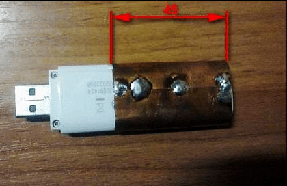
Upon completion of the assembly, at the opposite end of the cable that will be connected to the modem, you need to assemble the so-called matching device, provided specifically for such devices. For this purpose, copper foil is used, the same as in printed circuit boards. The performed antenna calculation for a 4g modem is the same as in the previous version.
If there is a connector for an external antenna, the cable is connected using a special adapter. After all connections, the antenna for the modem is considered ready for use. Setting the signal reception for 4g is carried out experimentally, by slowly rotating the structure around the axis until the clearest signal is obtained. Signal quality is determined by the number of dashes on the icon displayed on the computer or mobile phone.
Antenna Kharchenko for digital TV
For the operation of digital television, a range of decimeter waves is used. Therefore, before designing, Kharchenko antennas for DVB t2 should be made in order to maximize signal reception.
The design itself looks quite compact, it is made in the classic version of two rhombuses, as a result, a zigzag antenna without a reflector is obtained. Any conductive material can be used as a base, for example, a copper or aluminum conductor with a diameter of 1-5 mm. Tubes, strips, corners, profiles, etc. are also suitable. Copper wire 3 mm thick is best suited for these purposes. It is very easy to bend, level and solder. Further, it must be made in a certain sequence. TV cable resistance should be approximately 50-75 ohms.

The quality of a digital signal does not depend on distance, as it happens in analog television. In this case, when the TV antenna is working normally, the signal normally enters the TV receiver, but if there are failures, then there will be no signal at all. Accordingly, there will be no image. If there is a signal and it is normally received, then the image will be of the same quality on all channels. This factor must be taken into account when performing for digital TV, although individual settings may be different for a particular region.
Kharchenko's television antenna itself is made in a certain sequence:
- First you need to measure a piece of wire with a total length of 112 cm and bend it, observing the dimensions of the sections alternately 13 and 14 cm.
- After all the bends, two ends are formed, which must be cleaned to a distance of 1.5-2 cm. Loops are made at the ends and fixed to each other. The joints are completely soldered. Then, the central core is soldered to one of the joints, and the braid to the other. The result is a finished antenna or a double square.
- A biquad TV antenna requires a TV cable of approximately 3 meters. From the side of the antenna, it is stripped by 2 cm, and from the side of the plug - by 1 cm. The plug can be chosen at your discretion. It, like the wire, needs to be cleaned with a needle file or some kind of sharp object. Thus, Kharchenko's zigzag antenna for digital TV is almost ready for use.
- After soldering, all joints should be filled with hot glue from a gun. While the glue has not cooled down, its excess must be collected. It turns out at the same time reliable and elastic connection. On the antenna itself, the soldering points are also filled with glue.
Kharchenko antenna for phone
An external directional antenna can significantly increase the capabilities of a mobile phone and improve the quality of communication when a subscriber is in a remote area. It is not always possible to find the most suitable option on sale, so the Kharchenko antenna becomes the best way out for cellular communication made from improvised materials with their own hands.

The most affordable option is the standard design discussed above. Such an antenna should be sized according to the specific operating conditions. All necessary materials are sold in the hardware store. The simplest designs can be directly connected to the cable and do not require any special settings.
First of all, it is necessary to stock up on copper wire, with a diameter of 2-3 mm. You can take an insulated wire and remove the insulation from it. If connections are to be made without soldering, special F-type antenna connectors and connectors will be required. When it is planned to connect two Kharchenko antennas in parallel, you may need a reflector, which can be tin or aluminum. Joints are insulated with heat shrink tubing or electrical tape. Soldering requires a soldering iron.
Copper wire, prepared in advance, is bent and turns into a zigzag frame, which is two rhombuses. The sides of each of them are 80 cm long, and the total distance between opposite corners will be 226 cm. Next, the antenna calculator determines the connection point of these diamonds as the junction with the cable. A piece of cable, 50 cm in size, is soldered to this point, and an F-type connector is screwed to its opposite end. Next, the main cable of the required length is connected to the connector.

In some cases, the calculation of the Kharchenko antenna online involves the installation of a reflector that significantly enhances signal reception in a certain area. The design is the same as the antenna for T2, when the lower end of the frame and the reflector are connected to each other through the cable braid. For this purpose, a bolt 50 mm long is additionally screwed into the reflector, to which an F-type connector is attracted with a tie. Beforehand, a cable and a frame located at a distance of more than 40 mm are soldered to this connector. Thus, the Kharchenko antenna for a mobile phone, made independently in the simplest version, is ready for use.
For direct connection of the receiver to mobile phone a pigtail is used, which is a special wire. One end is connected to the antenna cable, and the other end is connected to the phone's antenna jack using a connector. In this case, there is no problem to calculate the antenna and no separate settings are required, it is enough just to position the antenna in the most optimal way, focusing on the quality of the received signal. It is recommended to install the mast with the receiving device as close to the house as possible, preferably near the window, in order to minimize the length of the cable.
Antenna Kharchenko
- The zigzag antenna, proposed by K. P. Kharchenko in the 60s, is very popular with radio amateurs due to its simple design, good repeatability and broadband.
Within the frequency range for which the antenna is designed, it has constant parameters and practically does not require tuning.
It is in phase antenna array of two diamond-shaped elements located one above the other and having one common pair of power points.
A zigzag antenna is most often used as a broadband antenna for receiving television programs in the ranges of 1 - 5, 6 - 12 or 21 - 60 UHF channels.
It can also be successfully used to work in amateur VHF bands by making
its for 145 MHz or for 433 MHz. A zigzag antenna with a reflector has a one-sided radiation pattern in the form of elongated ellipses both in the horizontal and vertical planes, and the rear lobe is practically absent.
With the seeming bulkiness of the entire system at first glance (Yags require much less and less consumption of materials), this system completely covers the range of 144-148 MHz (in fact, the band is much wider, about 12 MHz) with a good SWR not exceeding 1.2-1.3 and has the best radiation pattern. The gain of such an antenna is about 8.5 DBd, which is equivalent to about 4el YAGI at 145 MHz. A system of two such antennas already develops about 15 DBd. It has a more pressed radiation lobe, maximally adapted for conducting radio communications in the VHF bands. Antenna powered by a 50 ohm cable.
I made an antenna and improvised material in a literal sense. There was a sheet of galvanized sheet 0.8 mm thick from which I cut all the strips into antenna elements, and a couple of wooden slats. The fastening of the strips is made using a conventional riveter for 3-4 rivets in the corners. The width of all bands is about 40 mm, which provided a greater broadband for this antenna. The reflector strips are screwed to a wooden carrier (pre-painted) with ordinary screws.
- For the 145 MHz band, the dimensions are as follows:
The reflector has a length of 1050mm x 40mm for each strip.
Frame side 510mm.
The gap between the corners of the frames at the cable connection point - 40mm
Distance between active element and reflector - 300mm
The whole structure is visible and understandable from the photographs.
- The antenna can also be performed on the TV range.
Set it to horizontal or vertical polarization.
Below, the table for TV frequency channels is shown

Horizontal polarization

Vertical polarization
Antenna Kharchenko
or how it looks in nature :))
Resonance frequency 145.0 MHz
 |
 |
 |
| Pic 1 Fastening elements |
Pic 2 Antenna reflector |
Pic 3 zigzag element |
 |
 |
 |
| Pic 4 Power point |
Pic 5 carrier mount to the mast |
Pic 6 Racks and insulator in the center |
 |
 |
 |
| Pic 7 3 el.YAGI 145 mhz (for example) |
Pic 8 Everything is ready to installation |
Pic 9 Worth a beauty! |
ON-LINE calculator, for calculation
Kharchenko's antennas
Note: D - distance between antenna and reflector
Antenna Kharchenko
for low frequency range DCMA - 450-460 MHZ
Resonance frequency 452.0 MHz
- The antenna was made from improvised materials. Used old reflector grid
from the Polish VHF-TV antenna, which, due to its unsuitability, was already simply thrown away by me.
As an active element, I used an aluminum wire from an electric cable with a diameter of 4.5mm. The cable used is thin, RG-58/C, 50 ohm, 3 meters long. All calculations are based on the data of the online calculator. The difference in signal strength, according to the built-in
in the modem to the field meter, compared to the standard tail antenna, was more than 20db, that is, the readings with the standard antenna never dropped below -95db on the EvDO signal.
When the Kharchenko antenna was connected, the signal increased and is now at -72db and sometimes even up to -70db. The base station is 10 km away from the reception point. Due to its broadband, the antenna does not need to be tuned.
Thus, if you put a cable with low linear attenuation at these frequencies, install an antenna at a height of more than 15 m from the ground, you can easily block the distance to the DCMA BASE of more than 20-25 km and get access to the Internet, even in a very remote village))) )
 |
 |
 |
| Pic 1 Antenna ready to installation |
Pic 2 Set at level 2 floors |
Pic 3 View of the antenna from the window |
 |
 |
|
| Pic 4 AXESS-TEL modem CDMA 1-EvDO |
Pic 5 S-meter readings modem |
 How to Convert Video and Audio - Format Factory
 The best navigators for Windows Phone Navigation errors and how to fix them
 Instructions for using WinSetupFromUSB - Full description Creating a bootable flash drive windows xp winsetupfromusb
 Flash Drive Encryption Using an Encrypted Flash Drive
 Yandex Browser - extensions and themes come from Chrome, and its functionality even surpasses it
 Everything you wanted to know about the Sandbox server
 If the Internet does not work after reinstalling Windows ... A few tips Restoring the last working configuration